I’ve found myself many-a-times wanting a laser, especially for conducting experiments related to printing PCB’s. However, this is not a deep-dive into locally depositing copper onto a substrate from saturated copper sulfate solution using a laser, this is about building the actual machine itself.
Making the mechanics
The bulk of the build was done using aluminum extrusion, provided by OpenBuilds. This turned out to be the cheapest option, even when shipped to Norway (where I live), which was a pleasant surprise.
Well, maybe not cheaper compared to eBay, but OpenBuilds provide a kit-solution which proved to be just what I needed.
Speaking of what I needed, these were the specifications for my build, but if you want to scale this up, there is no reason why that shouldn’t work either.
I wanted a “build” surface of ~40×40 cm’s, with two axis. To maximize the quality of the final laser print, I wanted something really square and sturdy, so I built the bottom frame using two 500 mm OpenBuilds C-Beam Linear Actuator Bundles, connected to two 500 mm 20×40 aluminum extrusion.
I added a NEMA 23 motor for both actuators, but I later found I only needed one, your mileage may vary if you plan to use this for e.g. milling.
The 20×40 extrusion and C-Beam actuators were connected together with simple Cast Corner brackets, which wasn’t a good idea in the end. I had to remove the small peg in the brackets backside on the side connected to the C-Beam actuator, which admittedly was a rookie move. But hey, I am a rookie.
A better solution would probably be to use their angle corner connector, but I cheaped out and had to pay the price in elbow grease.
That’s the X-axis done. For the Y-axis, I chose a smaller linear actuator, namely the 500 mm V-Slot linear actuator bundle, with a NEMA 17 motor. This was attached to the C-Beam actuators with the above-mentioned fancy angle corner connectors.
The process of putting the C-Beam actuators and the rest of the extrusions up to this point was an hour of engineering bliss; everything came with pre-tapped holes and felt really high end. However, I was slightly disappointed to find that the end stops of the V-Slot actuator had to be fastened using self-tapping screws. This in itself wasn’t a huge deal, but after handling the heavy duty feel of the larger actuators and only un-pointy screws, I didn’t expect to have to handle any power tools.
Voila, the CNC mechanics were done!
The laser was to be attached to the gantry of this V-Slot actuator, and speaking of the laser.
Laser (!)
I was really nervous about importing a laser into Norway. I was expecting a bureaucratic nightmare, but in reality it was easier than I expected. At the time of building my laser CNC, the rules were something in the lines of: “You can import almost any type of laser, with any power, as long as it’s not intended to be hand held. Hand held lasers (read laser pointers) can only be puny”. I’m paraphrasing here, but that’s the jist of it. As long as you’re not intending to use the laser as a laser pointer, you can buy whatever laser you want.
Since this was “my first laser” (not a Fischer Price brand), I opted for a diode laser of between 1 to 5 W. After some looking around, I found a really cool polish company called Opt Lasers Grav, which specializes in engraving lasers. Again, I didn’t want an eBay laser with questionable documentation and quality, so I opted to spend a bit more on something that I had faith in.
I purchased the Universal CNC laser updated kit with PLH3D-2W laser kit, which probably was a massive overkill, but they had a great deal on it! In the end, I didn’t really use most of the parts of the kit, but as always with these things, you never know when you might need them. Also, I was a bit worried about driving the laser, and this kit includes a CNC adapter which provides power via an AC/DC power supply. The control logic to the laser module itself is also handled via the CNC adapter, and it has a very James Bond’y looking on/off/arm key.
The controls from the CNC control board (we’ll come to that later) is simply a PWM signal, which was connected into this box on the right-hand side, see the image below.
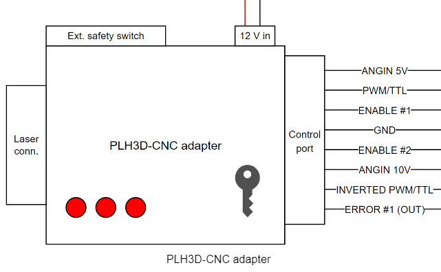
According to the documentation, I simply needed to supply the PWM/TTL input with a PWM signal from my main board, along with the ground connection as well. Overall, I must say I’m very pleased with my experience with the laser. Although lasers are scary sometimes, I wasn’t at all worried that I might break something in the laser itself, as the build quality and documentation was tip-top, 5 out of 5 toasters!
The laser module itself came pre-installed with a generic lens, but I opted for a high-resolution engraving lens, which I have yet to have tried.
At this point, I had spent quite a lot of money, around 300 EUR for the laser and 650 American freedom bucks on the CNC, but I was missing a crucial piece of the puzzle: The brains and power delivery, also known as the control electronics.
Electronics
As this project had already set me back a couple of hundred euros already, I asked my friends for some guidance into the deep rabbit hole which is cheapo control boards for CNC machines. After some late night calls and internet research, I ended up buying the very modestly priced BigTreeTech (aka BTT) SKR mini V1.1 with the aim to use the BTT TMC2209 stepper drivers.
Sounds good, doesn’t work as it’s known in the biz. After a while, I figured out that there were too many bodge jobs needed on the board in order for the SKR mini to work with the very nice TMC2209 boards. Instead, I ended up with the BTT SDK V1.4 Turbo 32 bit board, which is a tiny bit more expensive, but at least had documented support for the stepper drivers I wanted.
The TMC2209 supports silent stepping, which sounds nice, but moreover they are tried and tested to pieces. Also they are quite cheap.
So I’ve now ended up with a spare SKR mini board, which I don’t have any plans to use, so in the parts bin it went.
The beefier sounding SKR V1.4 Turbo 32 bit was a lot easier to get up and running with the TMC2209 drivers, but since I had designed my own CNC I needed to tweak some parameters, such as enabling silent stepping (‘cause it’s cool), sensorless homing, but more importantly change the XY step/cm.
To do this, I opted for using the Marlin firmware, which has support for the BTT SKR V1.4 Turbo 32 bit. It wasn’t too tricky to get the build chain to work, there are a lot of nice videos on youtube describing exactly that, for example this one.
I spent some time tweaking the code to my liking, and you can find my configuration.h and configuration_adv on my GitHub. This used the Marlin 2.0.x-SDK-V1.4-Turbo firmware, and you should be able to just copy-paste this into your configuration. For the DEFAULT_AXIS_STEPS_PER_UNIT, the default calculation is wrong, so I’ve included my own calculations in the comments above that define.
With the stepper motors moving at a reasonable speed, it’s time to look into the laser. Marlin and the BTT SKR V1.4 Turbo board supports lasers, but at this point I didn’t trust my coding skillz. Several points needed clarification: which pins are driving the laser, and is the PWM even working? In order to check this, I used my Saleae logic analyzer connected to the suspected output pins: 1.0, 1.26, 2.0 and NPWR.
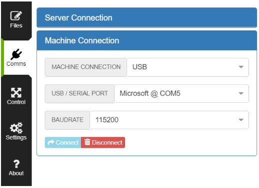
To control the SKR board, I used Laserweb, which is a free laser cutting software. I connected my device to the correct COM port:
I was now able to send G-code commands to the control board, and the G-code command for turning on the laser on 50% is “M4 S128”. The S-command goes between 0-255, where 0 is off and 255 is full power. And with the help of my trusty Saleae Logic 8, I was able to find out the correct pin:
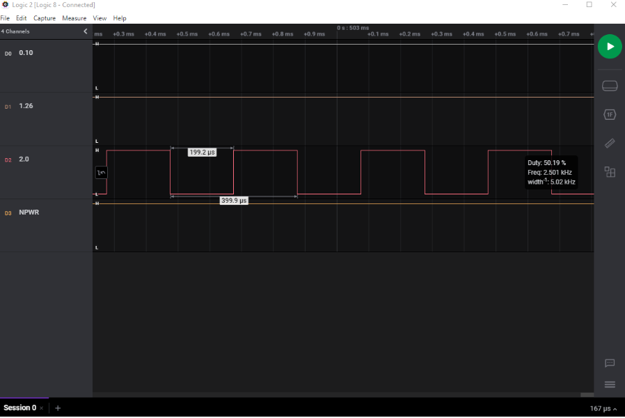
We can also see that the frequency is 2.5 kHz, and according to the laser documentation the recommended range is 5-10 kHz, which means that we need to update that before attaching the laser, which is done by changing the “#define SPINDLE_LASER_FREQUENCY” in Marlin.
I have that set to 5000 for now, but I might update that later on, your mileage may vary.
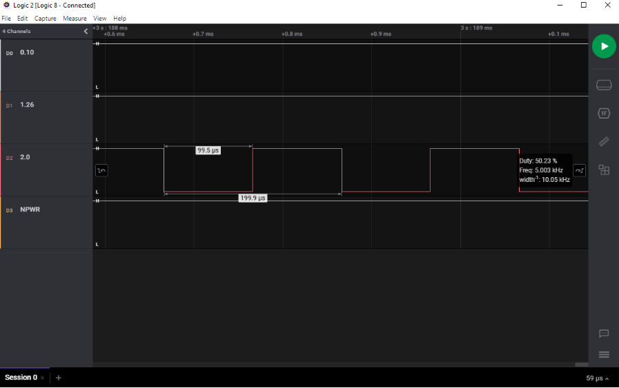
With that fixed, it’s time to attach the laser, and really that’s it.
We glossed over the power supply, but for this I have used a standard 12V power supply, for example the LRS-350-12 which has worked nicely for me.
Final Thoughts
The process of building this has probably taken more time than I have actually used “lasering stuff”, partly because my aim was to use this along with some chemicals which I’ve yet to acquire, and partly due to the smoking of when I eventually set something on fire.
That being said, I have tested it by burning some patterns into random pieces of plastic. But due to the smoke that develops, and the lack of garage/shed and filtration, I don’t currently have the courage to use this in my tiny apartment. So it’s currently taking up 70% of my desk surface, and mostly works as a conversation piece.
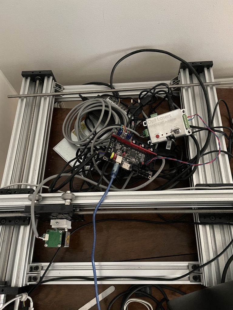
Since this is a very versatile and open platform, I have the choice to switch out the head to a CNC, pick-and-place, or something else in the future. I will end this piece with a picture of the current sorry state of my grand machine.