After reading this article you should feel that you know the very basics of radio systems. What are the main functions, components, what are the main challenges and where does it fit in the bigger Radio Access Network (RAN).
RAN
To understand what a radio is you must first know how a RAN is built up. I will take a typical RAN system as illustration, but these systems can look very different depending on generation, frequency band and deployment environment.
A RAN is the first set of network that a mobile phone, connected car or outdoor sensors (these are called User Equipment) will connect to. With antenna and other equipment setup tall on roof tops and cell towers to reach far and cover as much area as possible.
Area is divided into so called “cells” as a way to distribute the equipment for maximum coverage and least interference between each other. Each cell is connected to an antenna which converts radio waves into electrical signals before several steps of signal processing happens within the remaining equipment.
The signal is in the end made in to bits, bytes and packets before sent into the core network with routers and switches for what we normally call “the internet”.
For your understanding of equipment hierarchy you can look at following picture how multiple UEs are divded into cells, which are then connected by antenna to a radio before going through baseband and transported to core network.
Architecture
We are now ready to look closer into how the radio unit works. In following figure, we can see typical architecture of the downlink (radio transmitter). It would look the same just opposite order for the uplink (radio receiver).
The figure shows the five major functions in a radio, connected to an antenna and mobile phone. In the top you can see step by step what is happening for each function in frequency domain. In the bottom you can see it in time domain.
Resampling
The first step that happens after baseband processing (to be covered in another article) is for the radio to increase the sample rate. This means that the rate which the stream of data comes with gets increased such that more data/bandwidth can be combined into the same signal to be transmitted. When the sample rate is increased it is called “upsampling” and when it is reduced it is called “downsampling”, while the general term is “resampling”.
When upsampling is performed, it means that you insert new zero-valued samples to the signal. However, this will make spectral images appear as the new zero values will create steep changes to the original signal samples (non-zero valued).
As a second step, it is therefore necessary to interpolate the new samples between their neighbor samples by following the upsampling with a lowpass filter. For downsampling, a lowpass filter is necessary as well. Just that it needs to be the first step as it has to remove noise which will get folded otherwise when rate is reduced.
Data converter
The baseband processing and the first step of upsampling the signal are all made in digital domian. However, digital domain is only something we chose to use as it makes the signal deterministic and theories easier to handle. In reality, electrical signals and radio waves are analog signals.
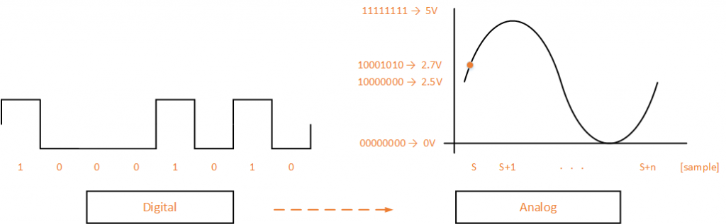
So we need to use a digital-to-analog converter (DAC) in the downlink and analog-to-digital converter (ADC) for the uplink. This will mean a stream of “ones and zeros” (e.g. a 8-bit sample: 10001010 bin = 138 dec) will be converted into voltage level (e.g 2.7V of 5V peak) continuous electrical signals in DAC (and vice versa for ADC). The conversion rate is what we call sample rate.
Frequency converter
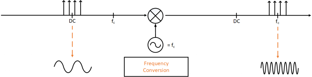
With an analog signal after DAC, it is now easier to shift the data from being centered around baseband / DC frequency up to transmitted center frequency. This operation is made by mixing the original signal with a pure sine of center frequency made by a dedicated oscillator.
It is possible to do this step in digital domain, before the DAC, but this requires very high sample rate to see so high frequencies in digital domain. It is just recently in time it has been possible for low frequency bands, high frequency bands still needs analog frequency conversion.
Power amplifier
Perhaps the most critical component of a radio is the Power Amplifier (PA). It sets the dimensions on many parts in the radio design. Except having a direct impact on the output power and therefore coverage/ cell size. It sets the size of cooling and requirements of the analog filter. Both of which are large and heavy (the biggest radios can weigh up to 100 kg).
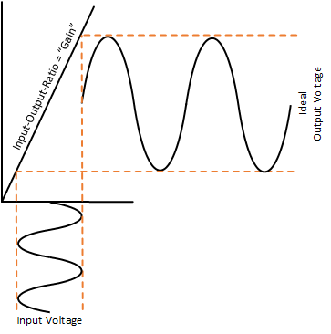
A perfect PA takes the original signal and increases its amplitude without distorting the signal. However, this is not possible as amplitude gain gets higher. So a trade-off between how much power to send out and how much distortion the system can tolerate needs to be handled.
In the uplink there is also an amplifier (low-noise amplifier, LNA), but instead of increasing the amplitude as much as possible. It just needs to increase it a little bit so it will be easier to detect for the frequency and data converters.
Filter
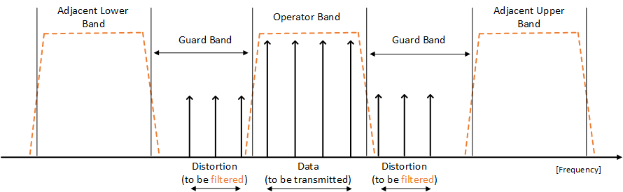
As said about the power amplifier, it creates distortion when amplifying the signal. This will both distort the data, but it will also create distortion outside the operating bandwidth. Since operators can a only transmit signals at their own bandwidth they own, it is not allowed to send signals with high distortions outside of it. So a filter must be used before signal is going out to the antenna.
As the signal now contians very high power, the filter will need to be big do it can attenuate all power in the distortion. For that a special cavity type of filter is used, which look more like mechanical block compared to small chips we use for small signals.
For the the uplink there is not high power, but the receiver is very sensitive to noise and interference so it will set hard requirements on attenuation levels.
Antenna
The antenna is not always considered as a part of the radio. In conventional systems it is setup separated in the cell tower with feeders to connect it to the radio. Modern Active Antenna Systems (AAS) has a lot of small antennas which can combine into one single beam, to be directed and steered to the user. In AAS products the radio and the antenna array are integrated to a single unit to reduce the many feeder cables that would be needed.
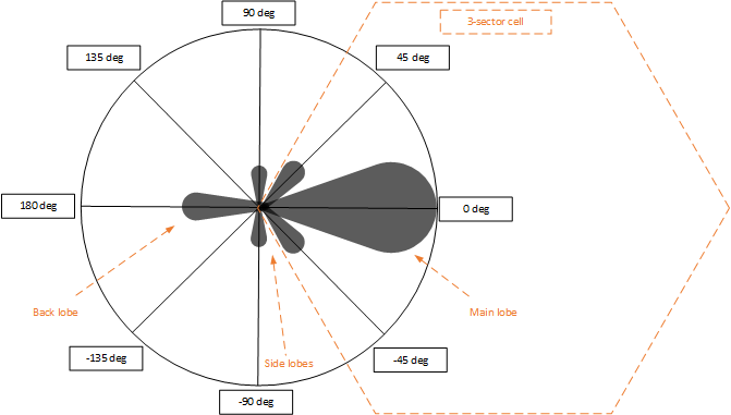
The following figure illustrates total antenna gain from an AAS array. It shows how concentrated these antenna gains are to one direction. Which is okay as the direction can be dynamically steered over the cell where users are the most. However, this comes with a cost of energy leakage in side and back lobes.
I hope this helps to give a basic but overall understanding of radio architecture. This article will be followed with further explanation on parts in the radio.