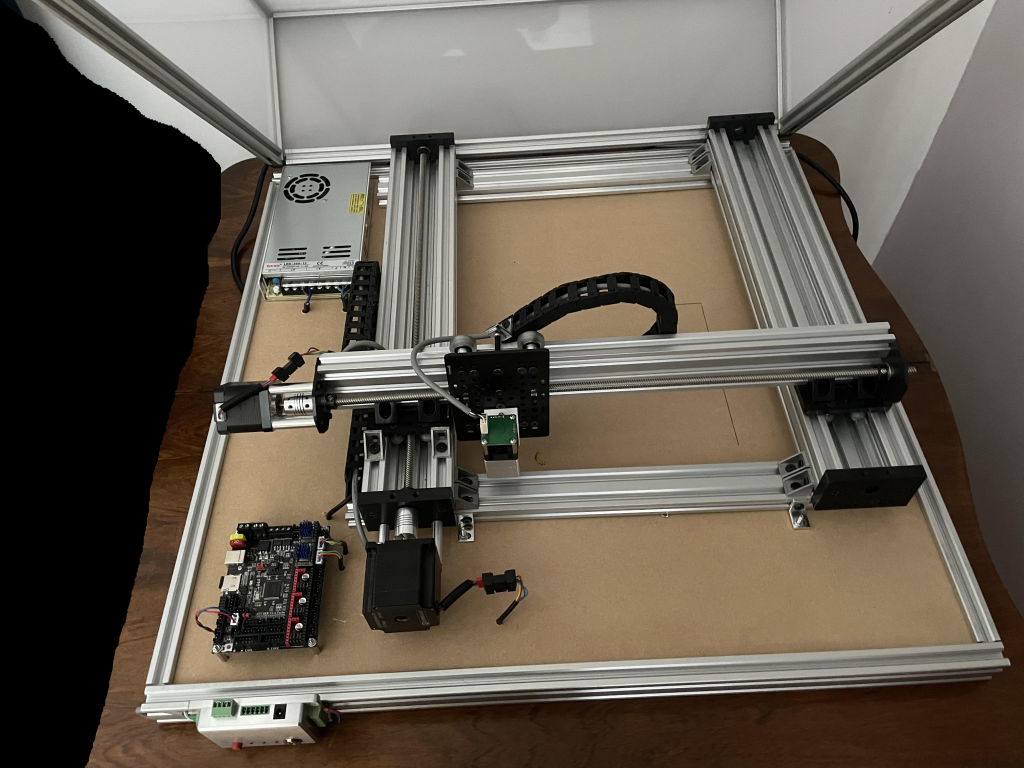
Last time I wrote about my CNC laser, the end result was a rats nest of wires, and I’d only tested it briefly.
Since then, a lot has happened in other parts of my life, and I found myself with a bit of time and an opportunity to finish the build for real. I’m also moving halfway across the world, and I’ll leave the CNC laser at my parents house, so it would be nice to make it too much of an eye sore.
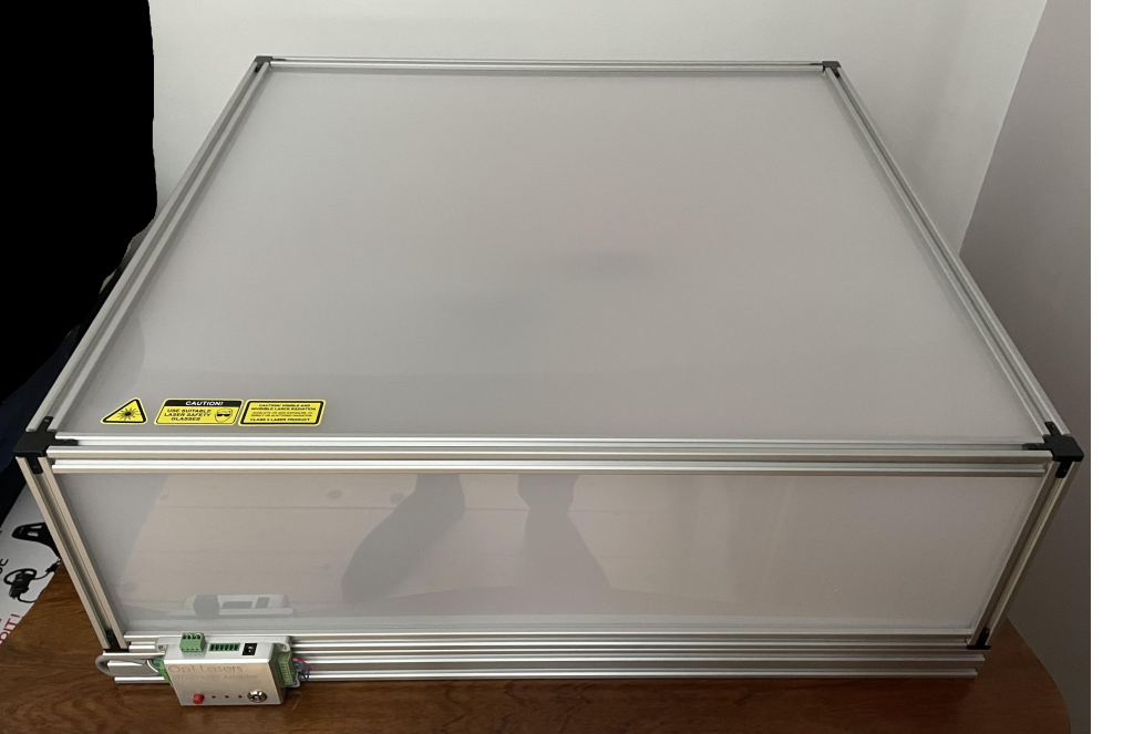
Picking up where I left off, I needed some way of protecting innocent bystanders’ eyes and somewhere to house the cabling. I.e. I needed a box.
I decided to continue the aluminum extrusion route, and build the framing out of 2020 and 2040 extrusion, where the “lid” is built using 2020 extrusion and 3-way brackets.
The base is built in 2040 extrusion, using normal corner brackets.
For eye protection I would have wanted black acrylic for the lid, but for the size needed (70x70x30 cm) only clear and opaque acrylic plastic was available within reasonable distance. The base plate is a 6mm MDF board, which is not the most sturdy in the world, but it does the job.
Putting it all together was very straight forward, it’s basically just building a box. The lid and base were held together using hinges.
The nice thing about building the base out of MDF board is that all the cable management could be housed underneath the board, making it look neat. It all took around a day to put together, and it’s alive and working again, although I haven’t really tested it thoroughly yet, but initial results of some test prints came out great. Below are some images of the finished CNC laser.
Next on the agenda was to properly calibrate the settings and test it out with some test prints. I got a test card print from the internet and quickly found out that I had some drift in the Y-axis.
I wasn’t sure if it was the GCODE generator, laserweb talking too quickly to the CNC or if my motor skipped steps. I couldn’t hear any obvious skipped steps, so I started on the software side of things. After a couple of hours of verifying the GCODE via a GCODE viewer, verifying that the communication between laserweb and the machine was OK (by writing some GCODE which repeated statements on where to go), I still had an issue.
Looking closer at the Y-axis motor, which is the one that is doing most of the heavy lifting, it became apparent that the motor was in fact skipping steps, but only in the beginning.
I then went back and checked my marlin settings. And I saw that the acceleration was very high, so I changed that to a more modest number (and did some testing) in the Marlin firmware and uploaded. But nothing changed. Through some more debugging I found out that only flashing the BTT SKR board will not save it to the EEPROM, instead a M502/M500 instruction combo is needed. Basically, M500 will save whatever temporary settings that have been found to the EEPROM, which would be lost after a reboot. Either way, with a reduced acceleration and some other minor settings tweaks, I was pretty happy with the results I got.
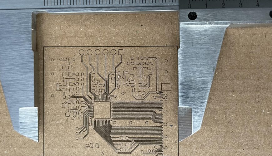
I have not done a full characterization of the performance of the CNC, but I was able to print this PCB outline:
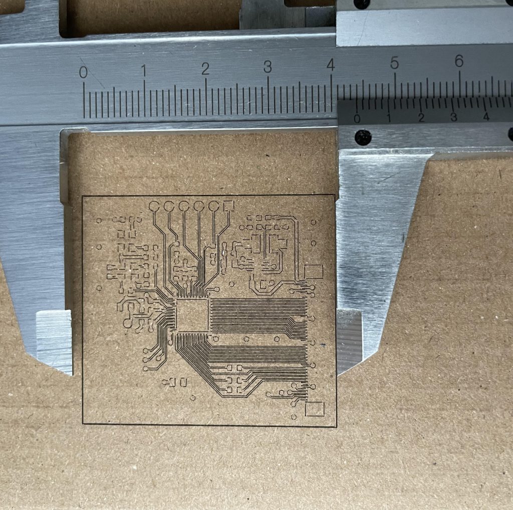
Now the eagle eyed among you readers might spot a small issue here: some of the lines do not link together. This is due to a combo of the delay from the BTT SKR board until the laser is actually turned on, which Marlin thinks is a really short time, but in reality it’s significant enough that the laser head has had time to move a bit before the laser beam is activated.
The image above is printed with laser cutting settings, 15% power at 700mm/min feed rate and a single pass. Reducing the feed rate will fix this issue for now, but the real fix is to trim the SPINDLE_LASER_POWERUP_DELAY and SPINDLE_LASER_POWERUP_DELAY in configuration_adv.h. Or somehow measure the delay, which could be done by printing squares at different feed rates.
So that’s where we are, the CNC laser works quite nicely with low feed rates, and has a pretty nice resolution if I can say so myself.
I could have spent a ton more time tweaking and fixing this issue, but I simply don’t have time. I’m moving half-way across the world in a week from writing this, and this beast of a machine is not coming with me (at the moment, if I stay abroad I’d have to ship it at some point).